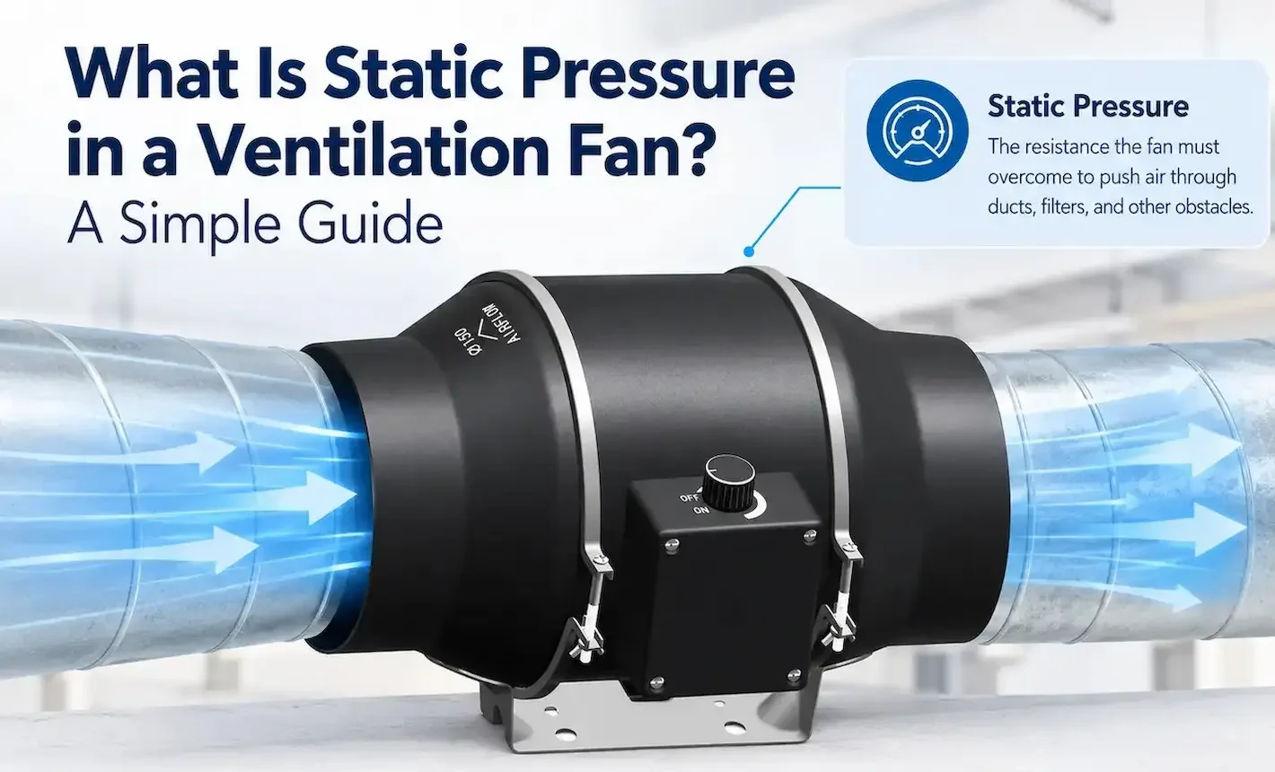
Long duct runs (>30 m) are where back-of-envelope pressure-drop estimates fall apart. The friction term grows linearly with length, but dynamic losses at fittings can dominate when bend density is high. This guide gives you a hand-calc workflow accurate to within ±10% of a full Comefri or Greenheck simulation.
Friction loss — the linear term
Use the simplified Darcy-Weisbach form: ΔP_friction = f × (L/D) × (ρ × V²) / 2, where f ≈ 0.02 for galvanized steel at typical Reynolds numbers, ρ = 1.2 kg/m³ for standard air, V is duct velocity in m/s, L is length in metres, D is hydraulic diameter in metres.
Rule of thumb for galvanized rectangular duct at 8 m/s velocity: ~1.0 Pa per metre of run. Doubling the velocity quadruples the friction loss — which is why long runs should sit at the lower end of the velocity table (5–7 m/s) where possible.
Dynamic loss — the fitting term
Each elbow, transition, branch and damper adds a fixed pressure drop expressed as ΔP = K × (ρ × V²) / 2, where K is the loss coefficient. Common K values worth memorising:
| Fitting | K Factor |
|---|---|
| 90° smooth radius elbow (R/D = 1.5) | 0.22 |
| 90° mitered elbow with turning vanes | 0.35 |
| 90° mitered elbow without vanes | 1.20 |
| 45° elbow | 0.13 |
| Branch take-off (45°, 30% of main flow) | 0.40 |
| Sudden contraction (50% area reduction) | 0.30 |
| Open butterfly damper | 0.20 |
| Square-edged inlet to duct | 0.50 |
Worked example — 45 m run, three elbows
Round galvanised duct, 400 mm diameter, design flow 4,500 m³/h. Velocity = (4500 / 3600) / (π × 0.2²) = 9.95 m/s. Friction loss ≈ 0.02 × (45 / 0.4) × (1.2 × 9.95²) / 2 = 134 Pa. Dynamic loss for three smooth elbows ≈ 3 × 0.22 × (1.2 × 9.95²) / 2 = 39 Pa. Total ≈ 173 Pa. Add 10–15% safety margin → 200 Pa target for fan selection.
Most commissioning under-performance on long runs traces back to cumulative dynamic loss being underestimated — not friction. Count fittings carefully and use realistic K values, especially for branches and dampers.