When choosing an inline duct fan, most buyers start by comparing airflow ratings. A fan rated at 350 CFM may seem like a straightforward choice for a ventilation project that requires a high volume of air.
However, there is an important question to ask: Will the fan still deliver that airflow after it is connected to ductwork?
The answer depends on the resistance of the ventilation system.
Duct length, bends, grilles, dampers, and other components can affect how much air a fan delivers. This is why a fan’s maximum airflow rating does not always represent its performance under actual installation conditions.
A fan performance curve helps explain the relationship between airflow and pressure, giving buyers a more useful basis for equipment selection.
In this guide, we’ll explain how to read a fan curve, what determines a fan’s operating point, and how the specifications of the TTTIGER DF150-M/A inline duct fan fit into the selection process.
What Is a Fan Performance Curve?
A fan performance curve is a graph showing how a fan performs at different airflow and pressure conditions.
It normally includes two important measurements.
Airflow (CFM or m³/h)
Airflow represents the volume of air moving through a fan over a given period.
CFM stands for cubic feet per minute, while m³/h refers to cubic meters per hour.
Static Pressure (Pa)
Static pressure is a pressure measurement commonly used to evaluate a fan’s ability to overcome resistance in a ventilation system.
Pascal (Pa) is a common unit used in ventilation product specifications.
On a typical airflow–pressure graph, airflow is shown on the horizontal axis, while static pressure appears on the vertical axis.
For many fixed-speed ventilation fans, available static pressure generally decreases as airflow increases.
The exact shape depends on the fan design, operating speed, and testing conditions.
Why Maximum Airflow Doesn’t Tell the Whole Story
Imagine installing an inline duct fan in two different ventilation systems.
The first system uses a short, relatively straight duct.
The second system uses a longer duct with multiple elbows, an exhaust grille, and a backdraft damper.
Although the fan is identical in both installations, the airflow delivered may be different.
The second system is likely to create more resistance, which can reduce the amount of air moving through the duct.
This happens because a fan must generate enough pressure to overcome the resistance of the connected system.
A maximum airflow rating is often determined under low-resistance conditions. It should not automatically be treated as the airflow available in every installation.
Similarly, maximum static pressure and maximum airflow normally represent different operating conditions.
A fan rated for 350 CFM and 360 Pa should not be assumed to deliver 350 CFM while simultaneously overcoming 360 Pa.
To understand whether a fan can meet a project’s requirements, we need to look beyond these two headline figures.
A Practical Example: TTTIGER DF150-M/A Inline Duct Fan
Let’s take the TTTIGER DF150-M/A as a product example.
The DF150-M/A is a 6-inch inline duct fan equipped with an EC motor. It is designed for use in compatible duct ventilation systems.
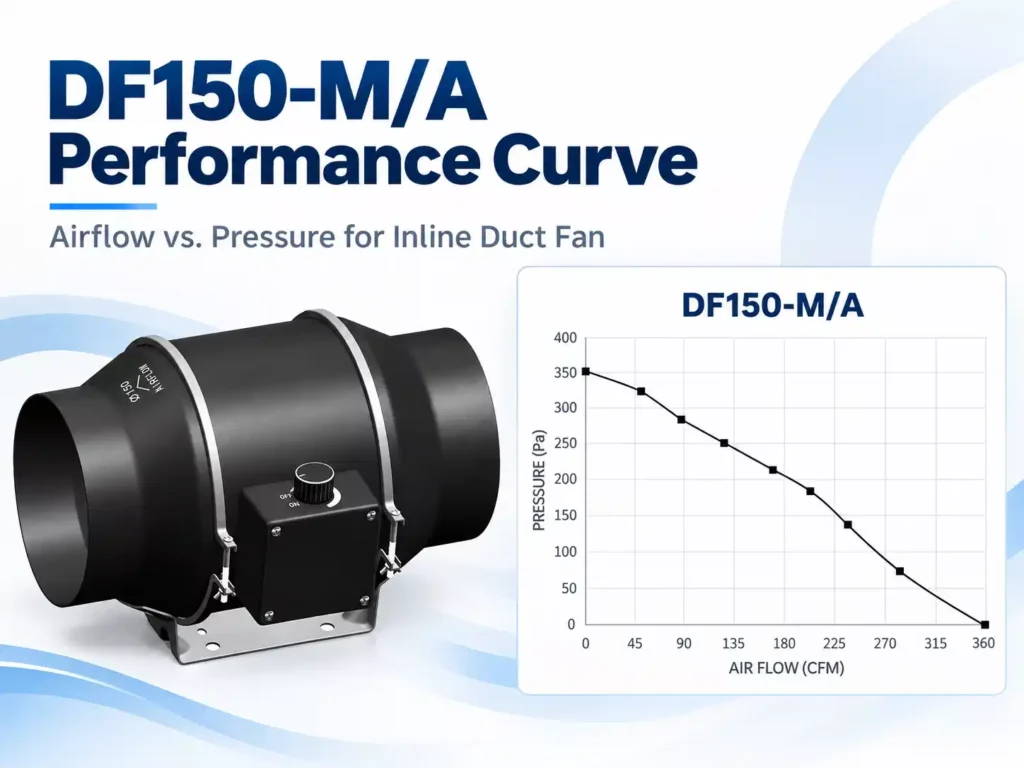
According to the supplied product specifications, its main parameters are:
| Parameter | DF150-M/A Specification |
|---|---|
| Fan Size | 6 inches |
| Motor Type | EC Motor |
| Voltage / Frequency | 100–240 V / 50–60 Hz |
| Rated Current | ≤1.0 A |
| Rated Power | 50 W |
| Motor Speed | 2500 RPM |
| Airflow | 350 CFM |
| Static Pressure | 360 Pa |
| Noise Level | 32 dBA |
These specifications provide a useful overview of the product.
The airflow rating tells buyers the stated airflow capability, while the static pressure rating provides information about its pressure capability.
The EC motor, power rating, and rotational speed are also relevant to the fan’s operating characteristics.
However, the specification table alone does not tell us the precise pressure available at every intermediate airflow rate.
For example, if a ventilation project requires 220 CFM at 150 Pa, we cannot confirm from the maximum airflow and maximum static pressure figures alone whether the DF150-M/A will meet that duty point.
We need the corresponding airflow–pressure performance curve for the exact model and operating conditions.
Why the Full Performance Curve Matters
A complete manufacturer performance curve would allow us to identify how much pressure the DF150-M can develop at a selected airflow rate.
It could also help buyers compare different operating points and evaluate whether the fan has sufficient performance for a proposed duct system.
The key takeaway is that a fan should be selected according to the required airflow at the expected system pressure, not simply by comparing the highest numbers in a specification table.
What Affects Airflow in a Duct Ventilation System?
The fan is only one part of the ventilation system. Several installation factors can influence its actual airflow.
1. Duct Length and Diameter
Air moving through ductwork experiences friction.
Longer duct runs generally create greater friction losses, while an undersized duct may increase air velocity and resistance.
Selecting suitable duct dimensions helps reduce unnecessary pressure losses.
2. Elbows and Bends
Every elbow changes the direction of airflow.
Sharp bends, particularly those installed close to the fan inlet or outlet, may affect system performance.
Where practical, duct routes should be kept reasonably short and direct.
3. Grilles and Backdraft Dampers
Ventilation systems often include exhaust grilles, air terminals, and backdraft dampers.
These components serve important purposes but can also introduce resistance.
For example, a backdraft damper helps limit unwanted reverse airflow when the fan is switched off. When the fan operates, air must pass through the damper, creating an additional pressure loss.
4. Flexible Duct Installation
Flexible ducts can be useful where installation space is limited.
However, compressed sections, excessive bends, and sagging can increase airflow resistance.
Careful installation is important for maintaining the intended airflow.
5. Inlet and Outlet Conditions
A fan installed immediately beside a sharp bend or restrictive fitting may perform differently from one operating under favorable laboratory conditions.
For this reason, the manufacturer’s installation instructions should be considered alongside the fan performance data.
How to Read a Fan Curve in Three Steps
You don’t need advanced engineering knowledge to understand the basic selection process.
Step 1: Determine the Required Airflow
Start with the ventilation requirements of the project.
The airflow needed will depend on the application, room characteristics, and relevant ventilation requirements.
For example, a bathroom exhaust system and a commercial ventilation system may have very different airflow requirements.
Step 2: Estimate the System Pressure Loss
Next, evaluate the resistance of the complete ventilation system.
This includes the duct route, elbows, dampers, grilles, and other connected components.
For a professional project, these losses should be calculated or estimated using suitable engineering data.
Step 3: Check the Fan Performance Curve
Locate the required airflow on the horizontal axis.
Then identify the pressure available at that airflow using the manufacturer’s curve.
Compare this value with the calculated system pressure requirement.
For example, if the required duty point is 220 CFM at 150 Pa, the fan must be capable of developing at least the required pressure at 220 CFM under the specified rating conditions.
If the fan cannot reach that duty point, another fan or a lower-resistance duct design may be needed.
Also consider power consumption, sound levels, allowable operating range, and installation conditions.
How Does Fan Speed Control Affect Performance?
Some EC inline duct fans can be paired with compatible speed controllers.
Changing fan speed affects the relationship between airflow and pressure.
A manufacturer may therefore provide different performance curves for different speed settings.
Reducing speed can lower airflow and may reduce electrical power consumption and operating noise under suitable conditions.
However, lowering the speed also reduces the ventilation capacity available to the room.
The selected setting should still provide the airflow required by the application.
It is equally important to verify controller compatibility. Not every speed controller is suitable for every EC fan model.
What Should Buyers Check Before Purchasing?
When comparing inline duct fans for a ventilation project, consider requesting more than a basic specification table.
The following information can be particularly useful:
- Airflow–pressure performance curve for the exact model
- Airflow available at the intended system pressure
- Motor type, rated voltage, power, and speed
- Sound rating and the conditions under which it was measured
- Compatible speed controllers
- Installation instructions and operating limitations
If the fan will operate in a system with long duct runs, multiple elbows, or restrictive fittings, performance data at the intended duty point becomes especially important.
These details help buyers compare products more accurately and avoid relying on maximum airflow alone.