Sizing exhaust airflow for a commercial kitchen hood is one of the most consequential decisions in any foodservice HVAC design. Undersize it and you get smoke escape, code violations and complaints from staff. Oversize it and the building loses thousands in conditioned air every month, plus the makeup-air system fights the hood instead of helping it.
This guide walks through the two methods accepted by NFPA 96 and IMC 507 — the perimeter method and the heat-load method — and shows how to reconcile them on a real project.
1. Define the cooking equipment line
Before any calculation, list every appliance that will sit under the hood and classify it by duty: light (steam tables, ovens), medium (fryers, ranges), heavy (charbroilers, woks) or extra-heavy (solid-fuel charbroilers). The duty class drives both the minimum capture velocity and the hood overhang requirement.
2. Apply the perimeter (hood-front) method
For a Type I canopy hood, the baseline formula is CFM = L (ft) × Q (CFM per linear foot), where Q depends on duty class:
| Duty Class | Wall-Mounted Q (CFM/ft) | Island Q (CFM/ft) |
|---|---|---|
| Light | 200 | 250 |
| Medium | 300 | 400 |
| Heavy | 400 | 550 |
| Extra-Heavy | 550 | 700 |
Worked example: a 12 ft wall-mounted canopy hood over a 6-burner range plus a flat-top griddle is classified medium-duty. Required exhaust = 12 × 300 = 3,600 CFM.
3. Cross-check with the heat-load method
Sum the rated sensible heat output of every appliance under the hood (manufacturer cut sheets give this in BTU/h). Convert to CFM using CFM = Q_sensible / (1.08 × ΔT), where ΔT is the temperature rise across the hood (typically 100°F for medium-duty).
If the heat-load result is more than 15% higher than the perimeter result, defer to the larger value. If it is lower, use the perimeter number — capture velocity is the binding constraint, not pure thermal removal.
4. Add the makeup-air balance
Code requires makeup air at 80–90% of the exhaust rate, introduced low-velocity (≤75 FPM at the cooking line) so it does not disturb capture. The remaining 10–20% comes from the building HVAC as transfer air, which keeps the kitchen at slight negative pressure relative to the dining room.
Common mistake: matching makeup air 1:1 to exhaust. The kitchen then goes positive, smoke spills into the dining room, and the hood loses 15–20% of its effective capture rate.
5. Final fan selection
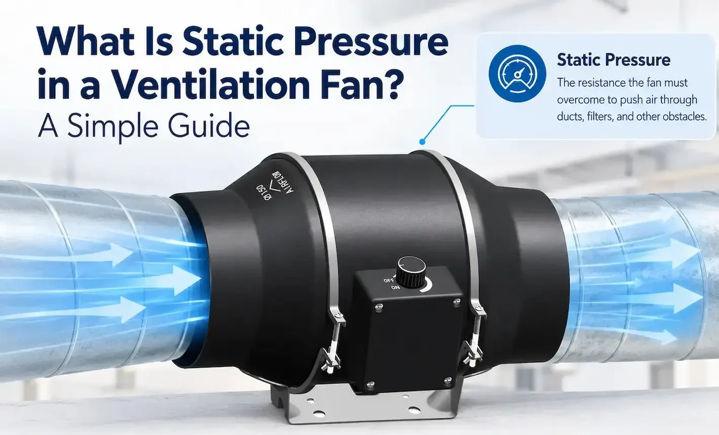
Add a 10% safety margin to the design CFM and select an upblast roof exhaust fan with sufficient static pressure to overcome the duct run, grease filter loss (0.4–0.6 in. w.c. when loaded) and termination loss. For our 3,600 CFM example, target 4,000 CFM at 1.0–1.25 in. w.c. SP — a TTTIGER UE-450-EC or equivalent will sit comfortably in its efficient operating band.